how about this?

Magnethead

Admin & Resident Techie
Staff member
Joined
Oct 18, 2005
Messages
11,233
Points
783
Location
Ft Worth Tx
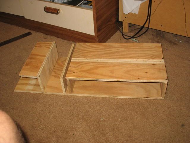
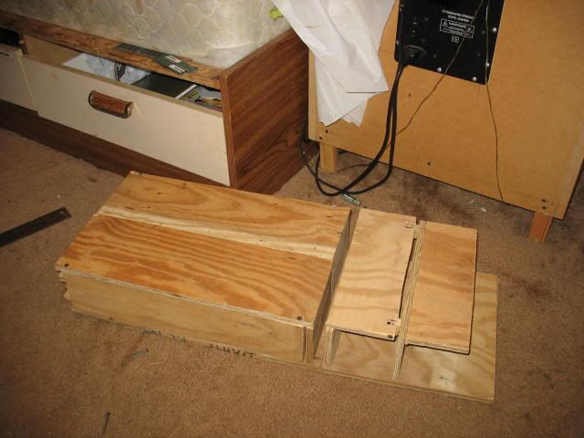
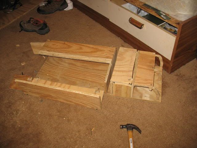
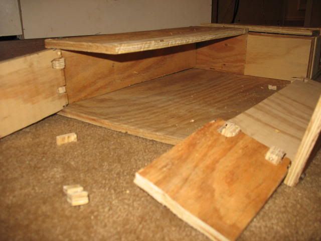
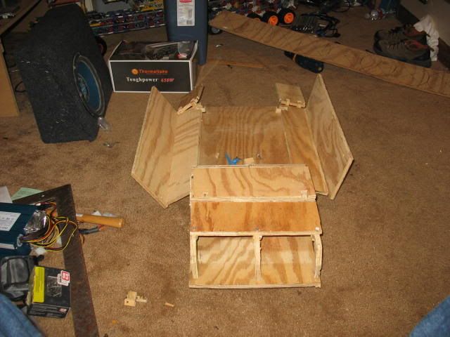
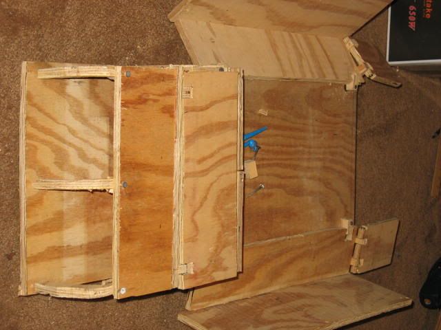
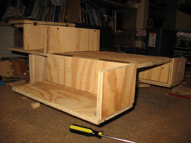
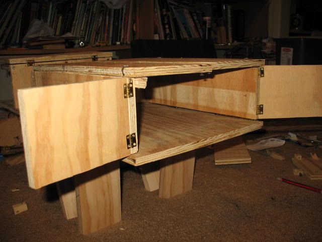
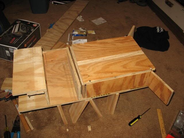
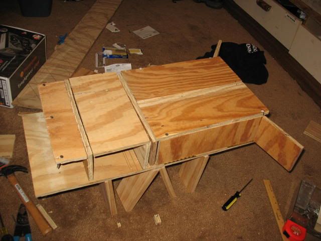
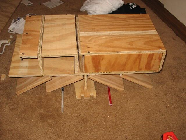
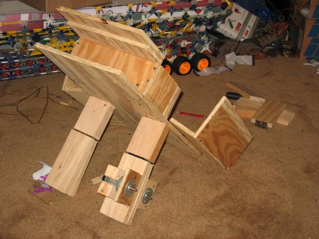
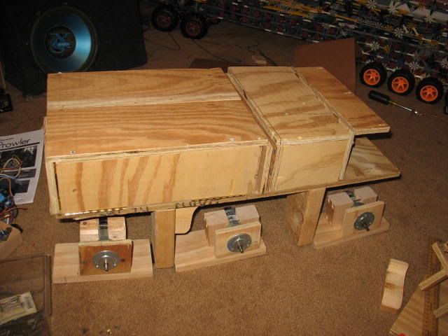
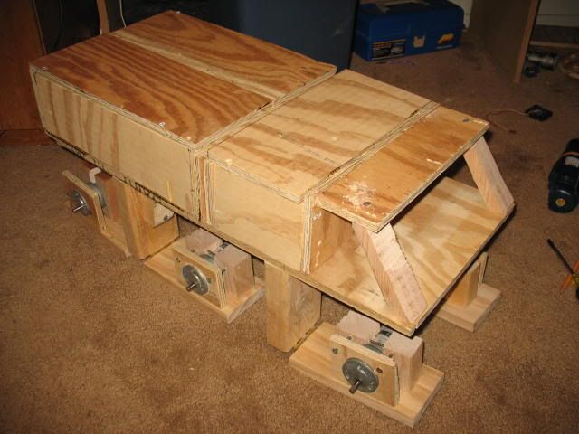
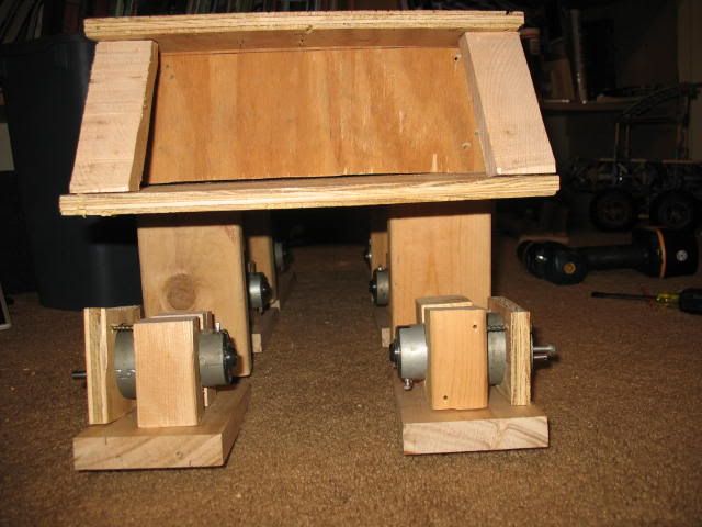
Those with good eyes might be able to make out the dimensions (in inches)..working with contacts right now to see if i can get some parts on discount. Would make a sweet RC vehicle. Skid steer FYI.

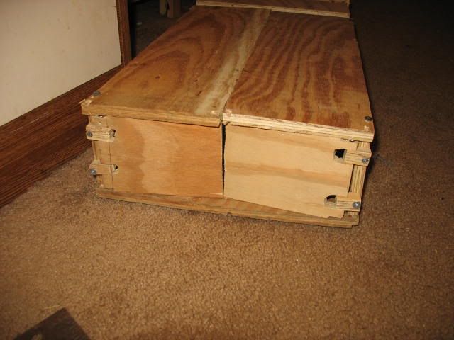
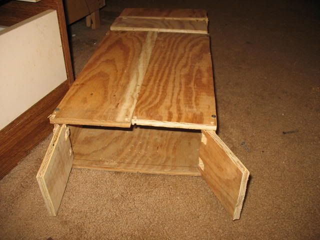
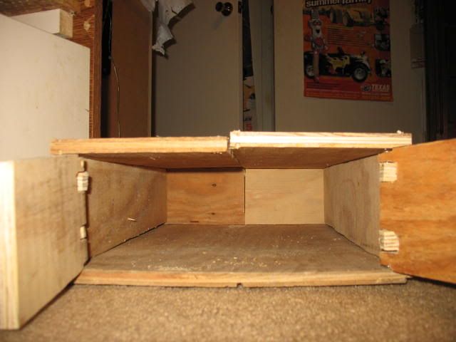
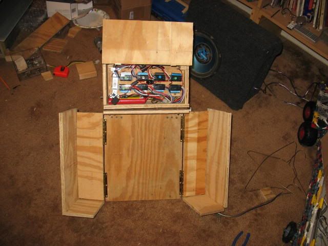
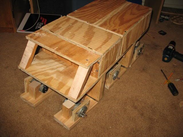
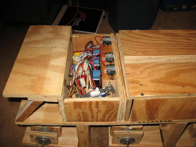
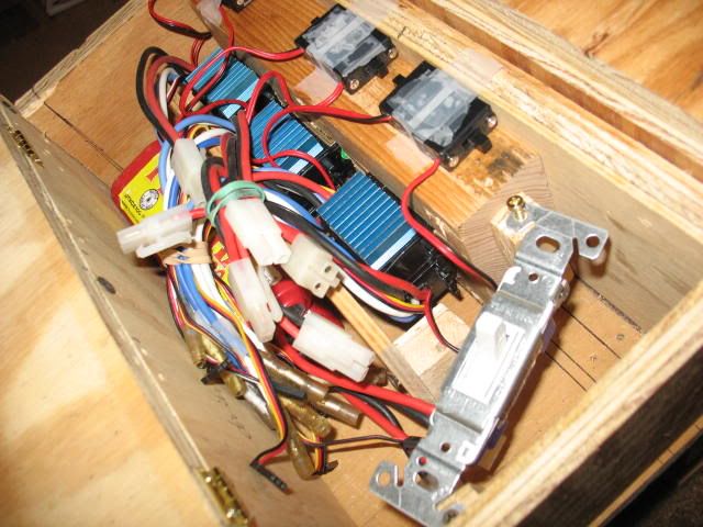
8 motors to drive it (one per wheel), 2 servo's to open the back, and thats basically it. All electronics stowed in that 3" area between the cargo bay and cab. Cargo doors open upward. Not sure what i'd ro with the 4th radio shannel, maybe run some light effects or something.

By the Numbers:

5.70": Inside to Inside Cab length Dimension
21.50": Inside to Inside Opening space Dimensions
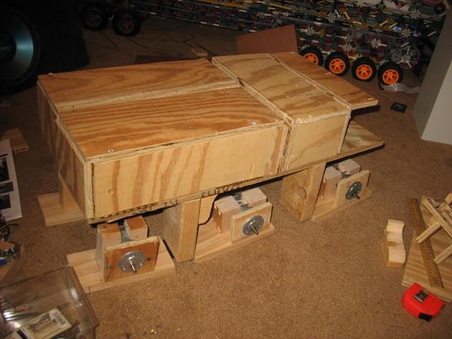
18.00": Inside to Inside Cargo Bay Dimensions
5.00": Outside to Outside (4" In-In) Cargo Bay height
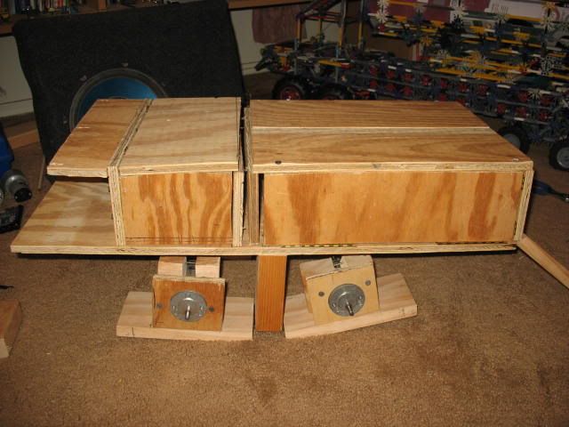
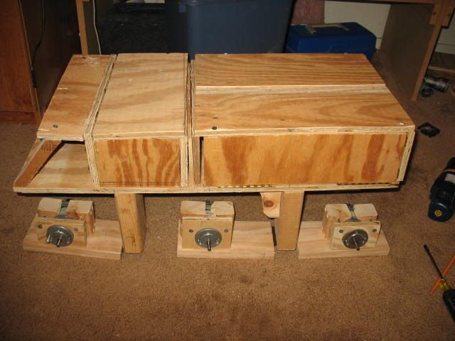
5.80": Bottom of chassis to ground Dimension, At ride Height
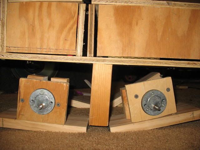
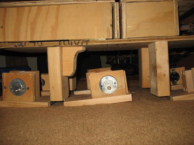
2.00": Motor Mount to Ground- Ground Clearance
10.80": Overall Height
3.20": Bottom of front bumper to Ground- Ground Clearance
30.90": Overall Length


8x8x0.gif


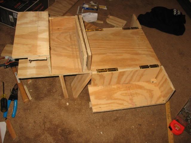
I'm awaiting word on the electronics, but i should have everything cut out and partially assembled tomorrow.
 
updated. I know it looks busy, but it's because i didnt take the time to make the hidden stuff with dashed lines.

8x8x0_2.gif
 
I'm still waiting for word on the electronics..but im no hurry on those.

All i have left above the chassis is the 2 endplates for the electronics compartment and the 3 windshield braces.

IMG_5990.jpg

IMG_5991.jpg

IMG_5992.jpg

IMG_5993.jpg
 
Got one side installed...Having real hinges would be nice, the ones i've made aren't that great since they're from 1/2 inch plywood.

IMG_5994.jpg

IMG_5995.jpg

IMG_5996.jpg

IMG_5997.jpg

IMG_5998.jpg
 
Damn I wish I had your free time. Hope it works. BTW, you cuttin that stuff with a Skil saw????
gee, i can't see how you can tell?

heck i switched over to the jig saw and that things so dull, i think a butter knife might be better..

I'm on the easy part right now. Once i'm done with the cargo bay doors, then i get to turn the wholoe thing over and start on the 4 link units....
 
Would look better made from molded plastic. Take your wood parts and make a mold. Then make the plastic pieces from the mold. A dremel would smooth out the harsh parts. It would also be lighter and more durable.
 
Would look better made from molded plastic. Take your wood parts and make a mold. Then make the plastic pieces from the mold. A dremel would smooth out the harsh parts. It would also be lighter and more durable.
I aint rich here, nor am experienced with fiberglass. I'll probably go out and buy some real hinges and some decent blades and what not and make a set of final panels that are alot more square, clean, and rounded in the case of the windshield mounts. That'll take out most of the issues i'm having with the man made hinges and panels not lining up exactly, not to mention make the dors open smoother and easier. Which will be good considering servo's are not exactly strong.
 
I was thinking you could melt down your army men. You don't hardly ever play with them any more.
Oh, and your mom called. She said to pick up your dirty socks from the floor and to put your shoes away.
 
I was thinking you could melt down your army men. You don't hardly ever play with them any more.
Oh, and your mom called. She said to pick up your dirty socks from the floor and to put your shoes away.
LOLOLOLOL

8x8x0_3.gif


That's the revised version. 3 inches shorter of base with a 1" longer electronics bay and a revised suspension that allows for approach and departure angles of greater then 170 degrees depending on suspension pre-load.
 
some quick notes to myself- the swayarn mounts will be chucks cut out of 2x6's that measure 1.5" tall (typical height in the 2" axis), 1" wide (on the axis parellel to the mounting shafts), and .75" deep (deep being from the side view), with a trapezoidally shaped end cover on the outside made from the 3/4" playwood. That should be well more than enough meat to hold the swayarms to the chassis while the suspension is moving over rough terrain.

Bump stops and limiting straps will be used to restrain the movement of the swayarms, with no tension so that at rest the arms are sitting on the bumpstops, which will be mounted as far outboard from the swayarm mount as possible to decrease mount stresses.
 
Well i'm starting to get stuff fabbed up. All thats left above the chassis is to get the left side cover for the electronics housing cut and put on, get hinges for the electronics cover, and figure out a better way to make the windshield mounts.


I cut the swingarms, and figured out that piano hinges will probably be better and more reliable then making my own cross pivots.

So i have to get 8 piano hinges and a package of small hinges to start out with, then measure the motors (which i'll get a week from tomorrow), make the mounts for those, mount the mounts to the swingarms, connect the swingarms to the adapters, adapters to hinges, and cut stop blocks out of 2x4's and 2x6's. Then It'll be time to finalize everything before sending it to the paint booth.

I'm going to do a thin base coat of black, with a second thin coat of dark green if i can find some, and maybe some gold or brown or something. So it'll be kinda like camo but not quite, it'll be a brown(gold)/green/black mixture.
 
Here's the radio system I'm looking at:

http://www2.towerhobbies.com/cgi-bin/wti0001p?&I=LXLGF5**&P=0

Has transmitter, receiver, and 2 servos- I'll have to buy 1 more servo, but that will be fine.

One servo will run the bay doors, while the second runs the left motors and third runs the right motors, with motors as either forward, off, or reverse.

Then when i get more money, get 8 mechanical speed controls ( http://www2.towerhobbies.com/cgi-bin/wti0001p?&I=LXKAL6&P=7 ) and get 3 speeds instead of 1.
 
I left the middle swingarms long, the outers should be 7.5" and inners 6.75" but they're all 7.5 for now. The descepancy is due to the mounting orientation to keep an equal set of wheelbases, the inners have to be shorter and of a steeper base angle then the outers, to keep all 3 wheelbases the same at rest.


Well, if it doesn't work...looks like it could be used to trap squirrels.
 
You are giving it one hell of an effort!! What are you making the drawings with?
DeltaCAD

Mocking it up so i can make the bumpstops (yes it WILL have a sprung suspension...or so i hope!) and adjust the inner swingarm lengths

IMG_6054.jpg

IMG_6055.jpg
 
here's your day's worth of engineering and design....Which actually took many hours to make in the case of the whole thing, and bout half an hour to design the linkage system for the doors.

baydoorlinkage.gif


I have to say that this is very intriguing and I envy your commitment. Last project I tried was trimming my toe nails and I still have a few days before I can walk on my feet again. That being said, this is very exciting and I can't wait for motors to come in. Hell, I popped some popcorn and grabbed a beer to read through this thread again.
 
Well, our school bot is finished and overwith, so i can concentrate back on mine. Would like to have the swingarms done by friday or next monday, Wherein i changed the swingarm design to make the arms swing with a more linear motion. The left side middle 2 motors are mounted and secured, I'm hoping i can source the shocks and springs (at give or take 14 in/lbs rate) from ebay, looks like it's littered in the ones i want. That in itself will be a trick setup. It currenty weighs, as pictured, 19 pounds per our digital scale.

oh, and those motors CANNOT turn within those mounts without extreme force. Once i get some thin sheet metal, i'll have some mounts specifically for those motors (i have the templates from the competition bot).

The motor front mounts are 3/8" plywood, and the back are a chunk of 2x4.

Basically, i started with some 4" x 3.75" bloks of the plywood, and a 2.5" long section of 2x4. Lined up one edge, labeled the mounting side, and clamped them together, with the plywood on bottom. I went to the drill press, put the stage 1/4" from the bottom of the hole saw (which was 1.5" diameter) with the extension all the way down (for a stop), and ran the press down through the 2x4 to the full extension stop. What that did, was put a 1.5" hole in the 2x4, and a 1/4" hole in the plywood. I then swapped a 2" hole saw into the press, lined up the guide bit with the hole from the other saw, and ran the saw down. This gave me a piece of 2x4 with a 1.5" hole and a piece of plywood with a 2" hole, with both holes having the same relative center point. Afterwards, i took the 2x4 to the jigsaw, where i cut it in half, went back to the press, made 5/8" deep countersink holes with a 21/64" drill bit on the press through one side of the 2x4, and followed it out with a hole matching the diameter of the screw. This allowed me to connect the 2 halfs back together to clamp onto the motor, but not before chamfering the openings for more surface area tto the motor casing.

I then drilled the holes to connect the face plate to the clamps, put those screws in, adjusted the depth, and set the motor assembly aside.

I then installed the 4.5" long segments of 2x4 to the bottom of the chassis, centered, and put 4 1.25" wood screws into them from above (the cargo bay), followed by one 2" screw per block. Once the drop mounts were attached, i mounted the swingarms (hinges) to the drop mounts, and attached the motor assemblies to the swingarms, in such an orientation that there would be exactly 8" between the shafts at full compression and 9.25" between them at ride height, or thereabouts. I then deemed that i could safely trim one inch of swingarm off, which will be done at a later time.

Between the "Cab" and the cargo bay is the electronics bay, which houses the on/off switch, 8 Electronic Speed Controls (ESC's), and the receiver once i get a radio kit. The Second to last picture shows how it should generally look once finished.

And here i am.

IMG_6151.jpg

IMG_6152.jpg

IMG_6153.jpg

IMG_6154.jpg

IMG_6155.jpg

IMG_6156.jpg

IMG_6157.jpg
 
Can you lift that thing by yourself?
Yes, easily. It weighs 19 pounds as pictured. One at the robotics comp weighed 22 pounds and only had 2 motors driving it....Mine will be around 25 finished with 8 motors...

be9, no, i'm building something not too dissimilar from this (Tatra 815 VVN)-

cz8x8t002.jpg
 
I'm switching from an 8x8 on 6" wheels to 6x6 on 10" wheels, to cust costs, weight, battery use, and make skid steer easier to use.
 
Well i got 4 of the 6 motors mounted and aligned, now that I have 2 less drive motors I can knock out 2 of the speed conrollers and give myself some more space in the electronics compartment.
 
Just have to bolt down the motor mounts... FYI eventually i'll have some sheet metal mount faces for the motors to mount directly to the swingarms to directly replace the playwood locator faces now.

FYI, that sub in the background is a 10" sub, for comparison of how big the wheels will be. I know the motors put out enough torque to crank the wheels, just a matter of transferring it TO the wheels without slipage.

IMG_6186.jpg

IMG_6187.jpg

IMG_6188.jpg


-edit:

Well, all the suspension and motor units are done and fastened where they should be for 10" wheel clearance. There should be about a inch and a half of gap between the wheels at ride height, the spindles are set at 11.5 inches. I have 12 shock and springs assemblies (6 4" long, 6 3" long) on the way, once i have those i'll figure out if i want to use 1 shock per arm or use a cantilever and use a long and a short on each arm. Meanwhile I'm going to set the project aside so I can clean up my room and the shop; There's at least a few onces of sawdust on my carpet floor and well over half a pound on the workbench under and around the drill press, plus another half pound or more in a pile in the shop from the table saw. I'm having the church group over sunday night so i dont got long to clean up!
 
It's a cargo Carrier. Something similar to this but on 6 wheels and completely out of proportion

cz8x8t002.jpg
 
It's a cargo Carrier. Something similar to this but on 6 wheels and completely out of proportion

cz8x8t002.jpg

See, I knew you should have melted down your army men. They would have been the right color even...

On 2nd thought if you had melted them down who were you going to have ride in your carrier.
 
All I have to say is you better throw some video of that thing's test drives on Youtube or something...

Looks like you're having fun.

Actually looks like one of those robo-wars vehicles.
 
for those wondering, the reason the A pillars are so big was so i'd have material to screw into to fasten them. I have put a mock steering wheel in it and will do the seat tomorrow...then put a plexi windshield on it if i can find any. I also found some 1/4" plywood for the motor mount faces to clean those up some so those will get done wednesday. After that, the shocks and springs should come in, so i'll design those mounts on friday and build and install them saturday..HOPEFULLY. Once all that is done, then i'll figure out the logistics of the electronics and see that all 6 motors work as they should while bypassing the electric controls. The radio kits are $100 and up (i may well be going to a 6 channel) so that will be the last thing bought; The Y connectors and the intermediate wiring is what comes first.

Left Y axis: left wheels control
Left X axis: Bay Door control
Right Y axis: right wheels control
Right X axis: Back door control

Bonus switch one: emergency Kill (power disconnect) switch (servo)
Bonus switch two: Head/Tail Lights switch (servo) (elsewise onboard)
 
I'll let the pictures do the talking. Nothing is set, thats why it doesn't look right. Can you say HUGE? Not sure what i'm going to want it to run over first...my bed or the dumpster :D

10-31-07 001.jpg


10-31-07 002.jpg
 
Back
Top Bottom