how about this?

So basically i've found that I have 3 good speed controls for 6 motors. Not a good equality basis huh?

so basically, it boils down to a pair of relays and i'll have to completely re-learn how to drive a RC car (because i'm going to have on and off only, as upposed to the intermediate speeds.....but I don't feel like getting 6 new controls at 25 bucks each!)

MOT_CON_F3.gif


http://www.distel.co.uk/DC_MOT_CON1.htm
 
What if you varied the wheel size... a little sandpaper might go a long way...

Just a low-tech thought.
 
Well, just got done with 2 exhibition runs- even with wires tapes together, it ran almost flawlessly. The motor mounts themselves need some help, but I have another exhibition tomorrow and ther next tuesday so i'm going to fix the wires over the weekend and use some of my scrap to fix the motor flex (need to create spacers and tie straps to keep the motors from flexing up and down as it skid steers) and re-solder or otherwise re-engineer the grounding of the lighting circuit.

I had declared today as the last chance finish date, and I made it. I got it running at 4 PM today. Got 3 motors on each speed control and they held up under full load (we through a PA amplifier in the bed).
 
Here's a hair of an update-

Bought a 1.2 GHz wireless mini color AV camera.

And successfully drove it around the house soley by watching the display on my computer monitor.

I'll post a recorded segment whenever I can put it outside.
 
so, 5 months later. I blew up the batteries in august, so i just bought a 7 amp gelcell 12 volt battery. Tower hobbies says it should hold up to my intentions, if not, It has a 90 day warranty.

Also, I'm going to put 6 wheel steer on it, money providing (goal: by my senior year, it won't be autonomous, but i'll be able to control it solely by video feed(s) to within an inch of whatever i'm going around)

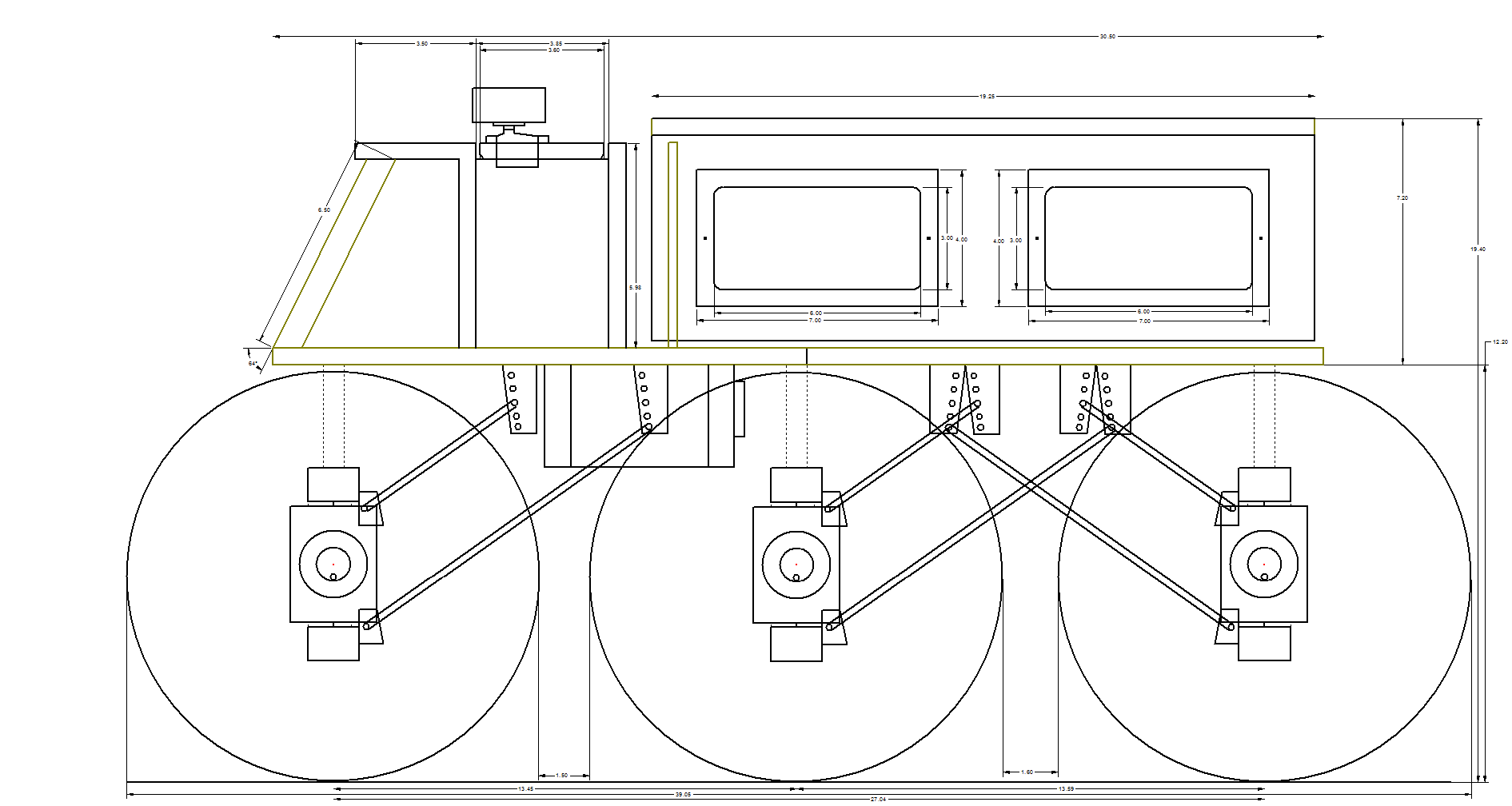
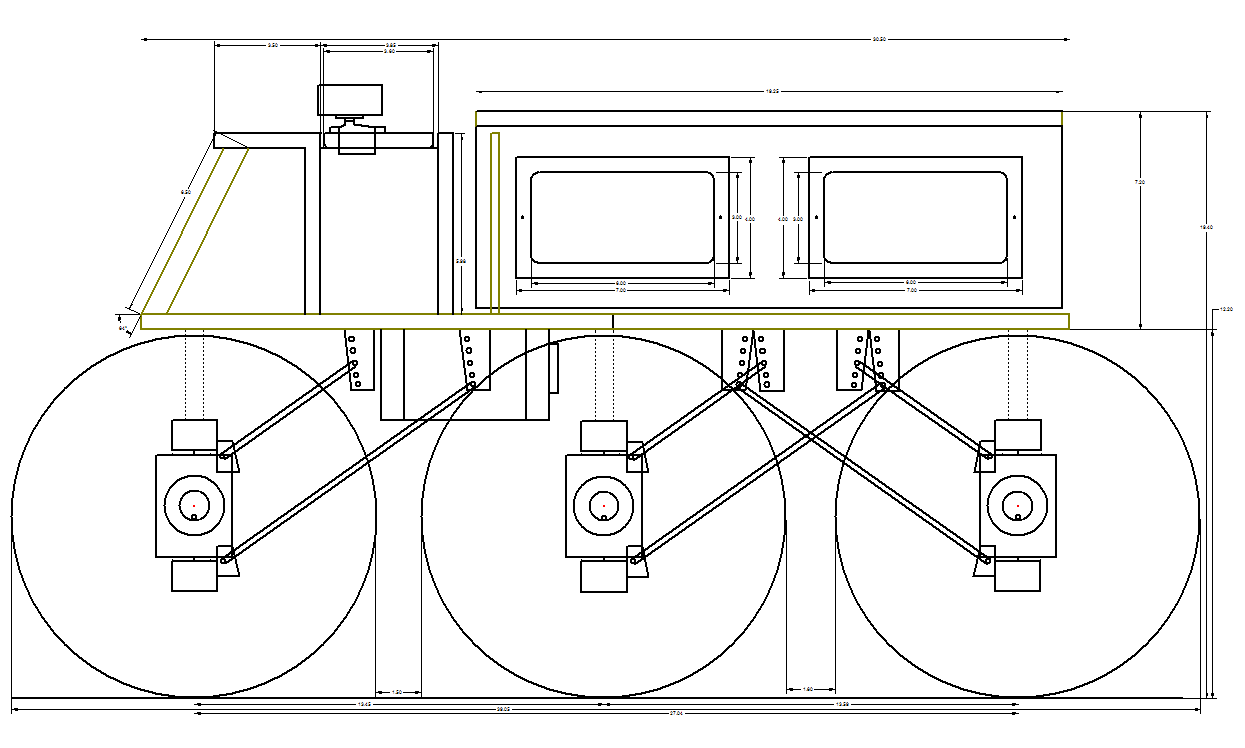
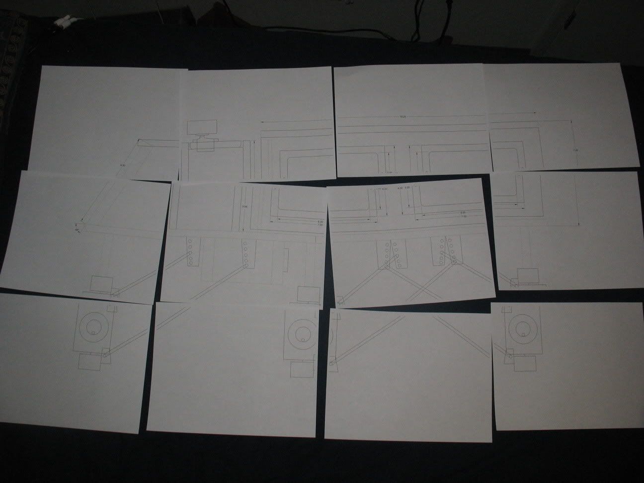
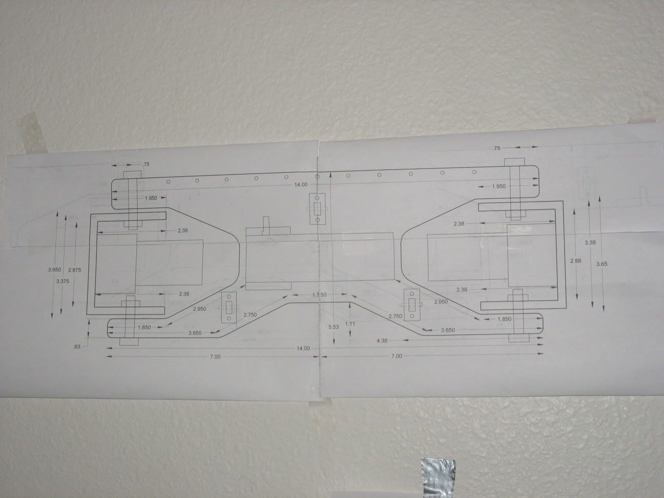
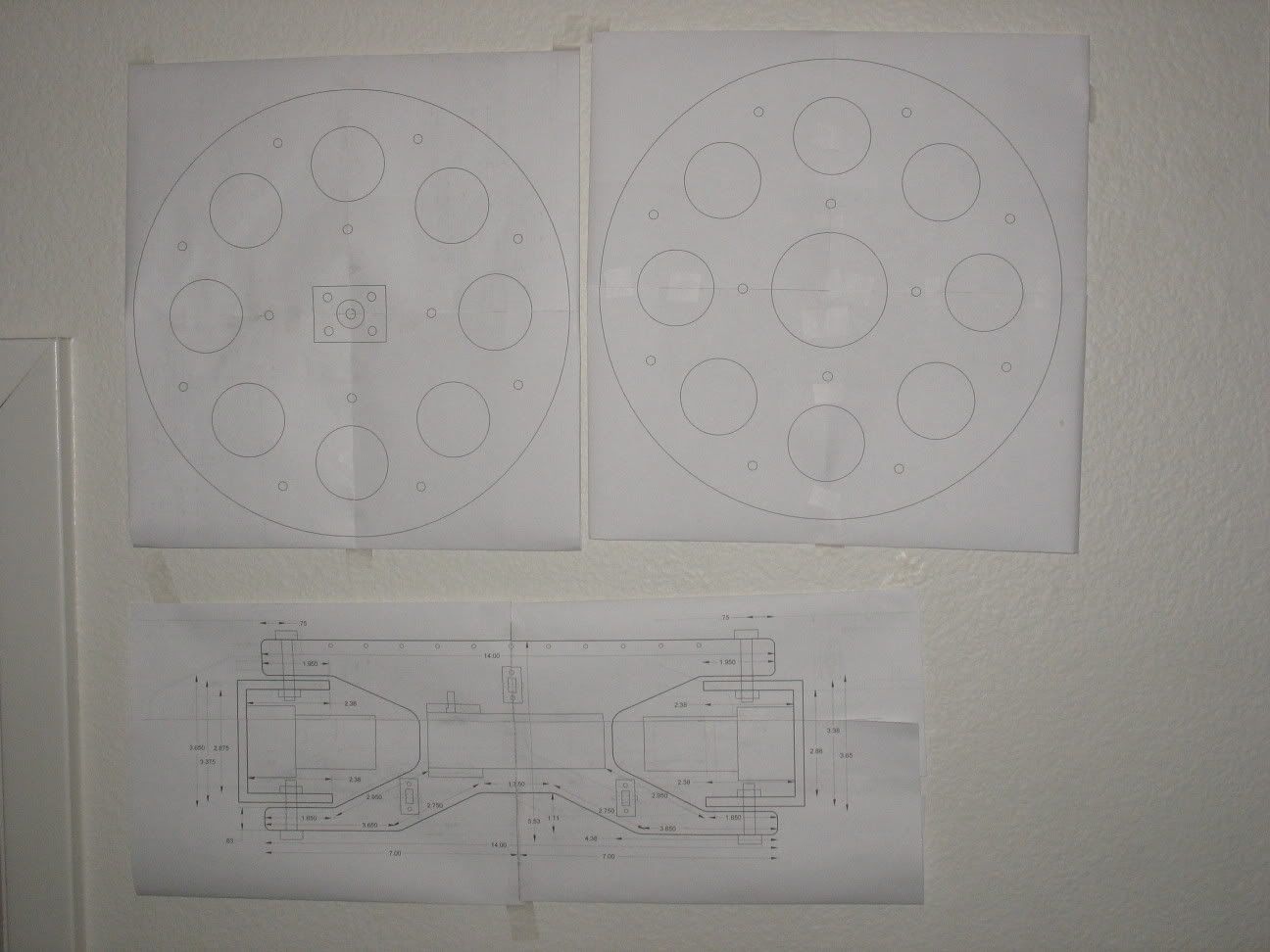
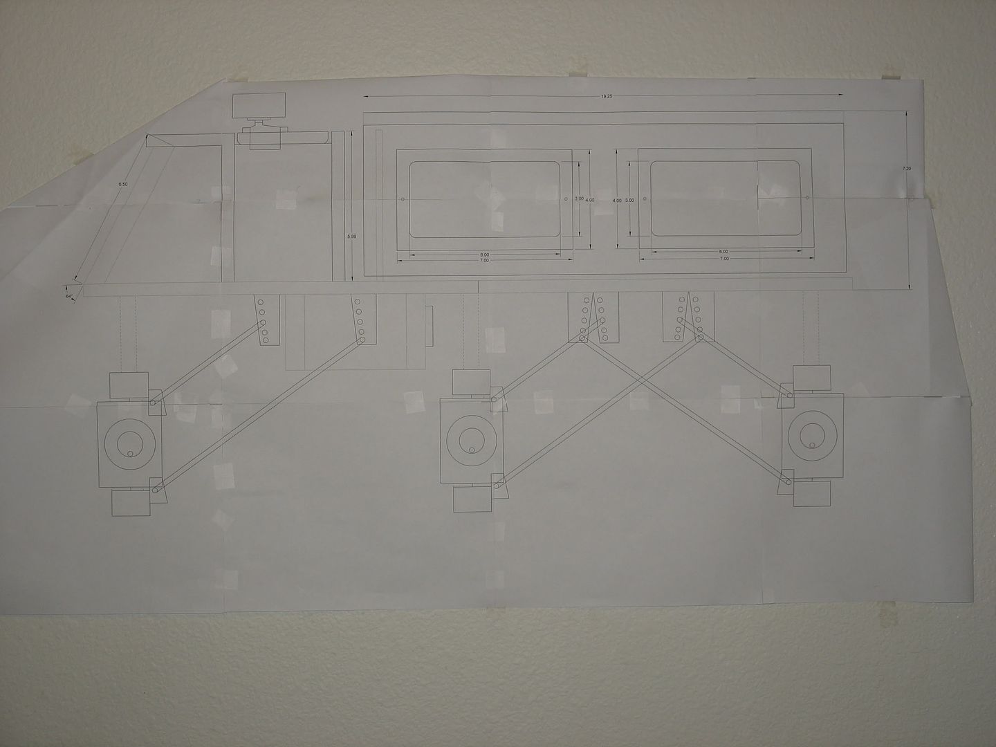
As of right now i'm thinking to basically make an AIRT2, I'll use the same camo templates (I kept them somewhere), but it will be longer, just as wide, 6 wheel drive/steer (crab walk or countersteer), and have 12" tall 1.5" wide wheels instead of 10" tall 1/2" wide ones now. The chassis will be 2 inches longer (I believe that's how it's drawn up so far), and the front/rear axles will be more outboard to make up the tire radius difference. Axles will be suspended by 4 shocks per axle (same as now) with a 3 link + track bar setup. So it should also be far more articulate compared to the current sway bars. It will use the same 7 amp battery, the existing 6 wheel motors plus a steer motor on each axle, plus a few more headlamps- 4 on the front axle, 2 on the outboard corners of the chassis (10 degrees pointed down), and 2 above the cab (pointed 15 degrees down).

The 7 amp battery will run just about the entire robot for the short term, but there will be more batteries down the road.


Big picture changes:

The camera will be re-located on top of the cab, and the mount will be double-sided, so that a second camera can be placed back-to-back with the first. This is how i'll get the close navigational tolerances. Ideally I'd like both camera screens to be able to appear on the same monitor at once, but not sure what exactly would need to be done wiringly to make it happen.
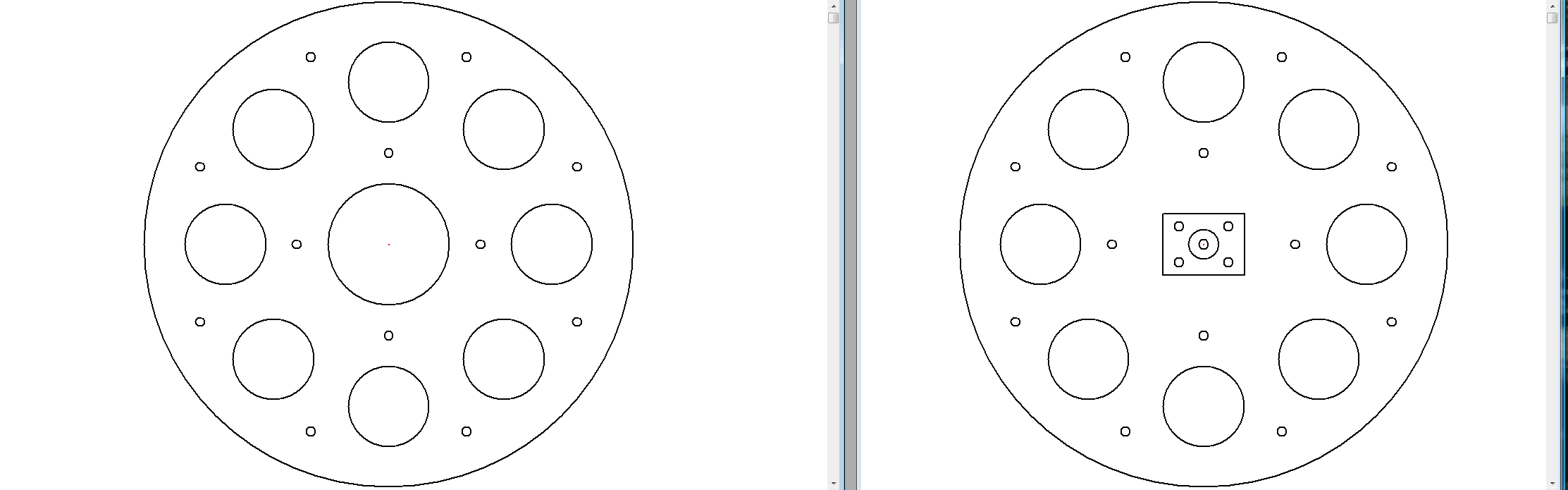
6 wheel steer

12" tall, 1" wide tires, wrapped in 2 layers of inner-tube

2-4" Longer

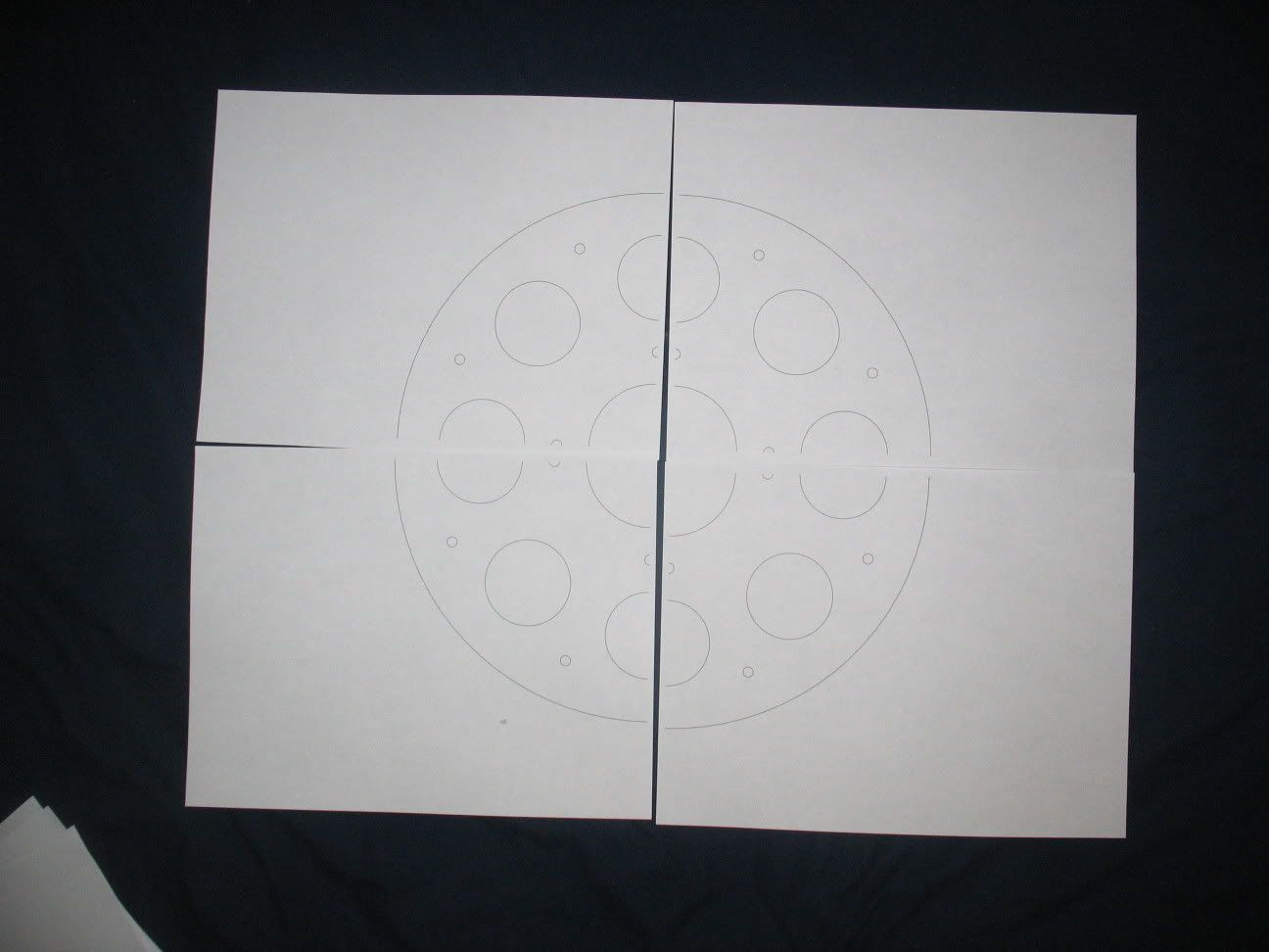
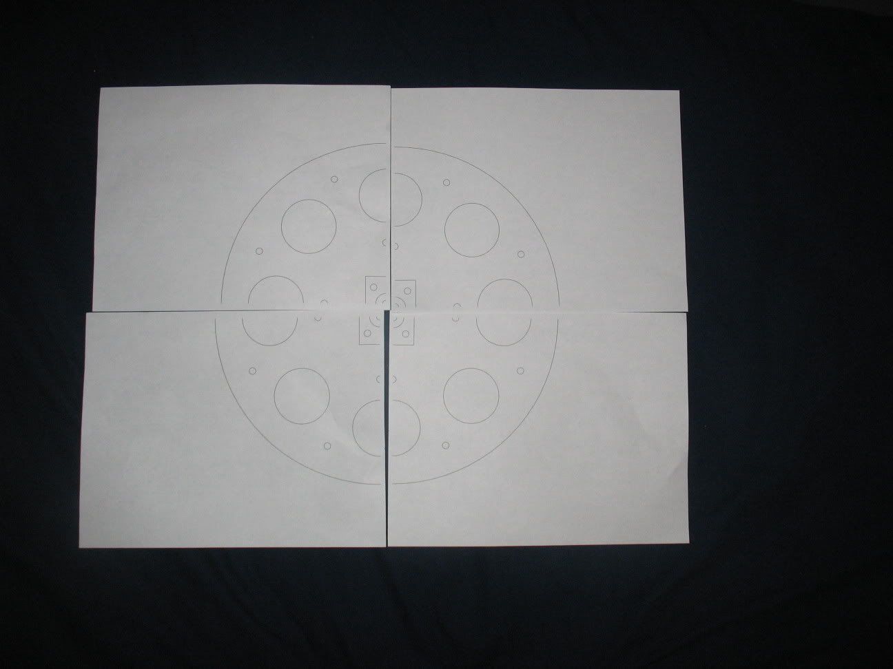
aluminum 1 piece cargo-bay doors with integrated windows (shuttle-style)

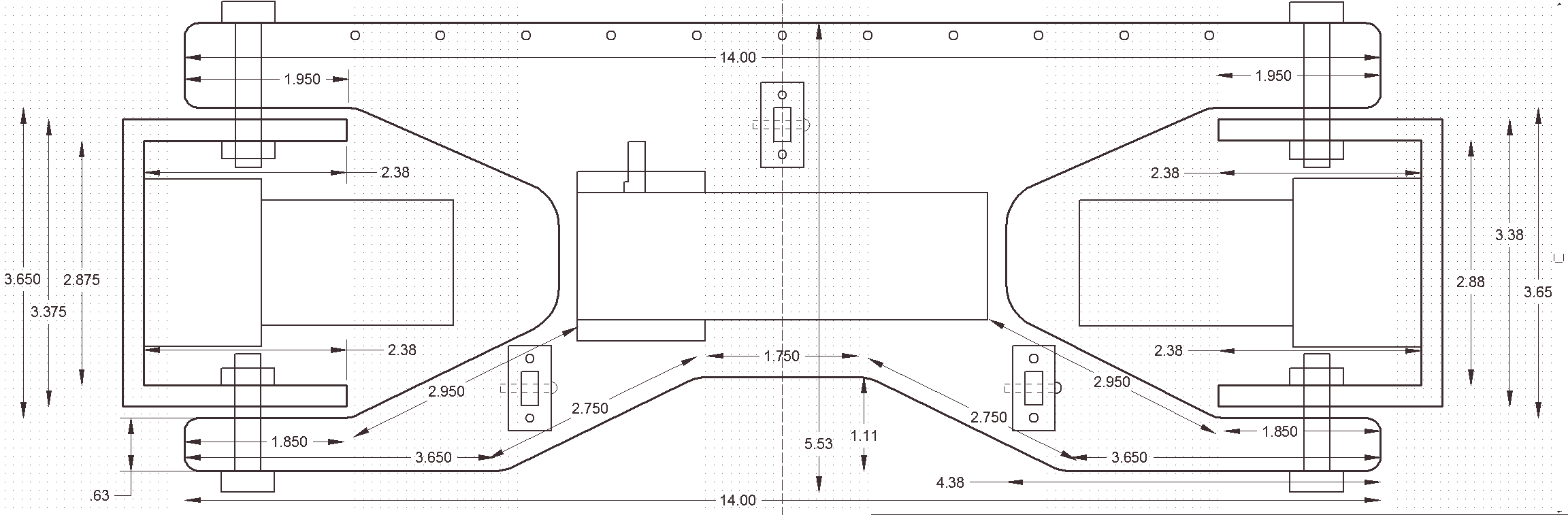
3 Link + track bar suspension

Three motor control units, 1 per axle

1/4" thick steel plate to reinforce weak areas of wood (suspension)

3/4" plywood base + electronics box, with 40mm fan on elecs

1/2" aluminum bulkheads + cab/battery bay

basically, the only wood will be the 3/4" base, the electronics box, and the 2x6 main suspension truss (with 1/4" steel plate bracing along the top and bottom fatigue lines).

The 1/2" aluminum plate I can get locally then cut down in the race shop (i'll try to trade the unused plywood for a little bit of spare shop time)

I should have a CAD version sometime soon. I have a rough sketch, just gotta digitize it.
 
Here's the CAD renderings:

High-res:


Low-res:


I forgot to color in the electronics box under the chassis in brown, but it will be wood also (black = metal, brown = wood, for most of it)

the side panels of the cargo bay will have the same design on the top panels, the 4x6" window with .1" plexi inlaid into it

chassis is 30.5" long, overall is ~40"
 
The one crucial thing that I see missing is the frickin' laser beam attached to front...
 
The one crucial thing that I see missing is the frickin' laser beam attached to front...
I could probably figure out how to rig a laser pointer to it (maybe to the camera mount). Just a matter of if I wanted to.

Does sound like a neat idea though

Materials: 3/4" plywood (real plywood, not MDF or composite)

42" 2x6" lumber (6 ft chunk, make a spare truss or two)

1/2" aluminum plate:

Cargo doors: 2x [ 19.25x6 ] + 2x [ 19.25x6.5 ]

Bulkheads: [ 12x6 ] + [ 12x5.5 ]

cab: 12x3

elec cay: 12x3.5

Suspension: 9x [1.25x1.5 ]

1/4" steel plate: Suspension links, track bars, axle truss reinforcement, bay door links, steering tie rods, motor mounts

clearcoat (spray-on or otherwise)
Here's the steering arrangement.

 
3/4" plywood (real plywood, not MDF or composite) $15

42" 2x6" lumber (6 ft chunk, make a spare truss or two) $12

1/2" aluminum plate: 42"x20" ~$75?

Cargo doors: 2x [ 19.25x6 ] + 2x [ 19.25x6.5 ]

Bulkheads: [ 12x6 ] + [ 12x5.5 ]

cab: 12x3

elec cay: 12x3.5

Suspension: 9x [1.25x1.5 ]

1/4" steel plate: Suspension links, track bars, axle truss reinforcement, bay door links, steering tie rods, motor mounts $20

clearcoat (spray-on or otherwise) $5

steer motors $120 ($40x3)

limit switches $15

Locking collars $20

Material cost is "cheap" until you get to those steer motors. 8 RPM at 12 volts, right angle drive. $282 total, $162 in materials and then the 120 in motors.
 
So, found a flaw in my wheel idea. I was wanting to piggyback a pair of 3/4" wheels together to make a single 1.5" wide wheel. Well, the way I have to mount the wheels to the motor shafts, I can't use a 3/4 inch wheel- a pair of 1/4" wide set-screw collars plus a 1/4" mounting plate won't clear a 3/4" board. Plus, there wouldn't be enough 3/4" material for 12 1 foot wheels.

So now, I'll have material for the 3/4" wheels, but will have to find 6 square feet of 1/2" material.

mounting: put lugs through plate, put hub on shaft, lock down both collars, place inner wheel on shaft, put outer wheel on lugs, put locknuts on lugs and tighten. Line up bolt holes (the 12 1/4" holes) and insert bots, lock down with locknuts.

Inner wheel on left, outer on right.

So, I have the chassis, suspension, and wheels defined. Just a matter of getting solidworks (If I can) to 3Dize it, then buy everythign and start fabbing.


For lighting, they'll be 2 orange LEDs on each cargo door, instead of 1 on the old bot, due to the increased size. The first LED will be at the top of the leading edge (before the cargo bulkhead), while the second will be at the far top rear corner, to clear any cargo. At these locations though, wires will be harder to hide. By using metal components (and thick wooden ones), I am hoping that wire management may be easier- I can use a drill press to safely drill 3/16" or 1/4" cabling tunnels as long as the drill bits and math will let me through the doors and chassis to hide wires without comprimising strength or derating the visual factor.

Motor and lower head/tail lights will be ziptied to the top of the 3 link suspension then follow a loom to the electronics box.

The chassis headlights will follow the cable tunnels back 3" inboard, before popping out the bottom to follow more loom.

The cab headlights will have tunnels running through the cab ceiling, which will meet up to the bulkhead between the cab and electronics bay. The tunnels in the bulkhead will then run down to the electronics box.

The cargo bay LED's will have tunnels running vertically through the doors of the bay. Holes will be tapped on the inside wall, where the wiring can enter the door, then run down through the door. Holes through the chassis will line up with the tunnels from the bay doors, then the wires will follow a loom to the electronics box.

The Electronics BAY will have the battery(ies), cargo bay servos, power switch, and RF Reciever(s).

The Electronics BOX will have the 3 main drive speed controllers, the 3 steering speed controllers (to slow the steer motors down more)

http://www.superdroidrobots.com/shop/item.asp?itemid=848&catid=5 Drive motor controller

http://www.superdroidrobots.com/shop/item.asp?itemid=847&catid=5 Steer motor drive
 
Wow. This thing is going to be huge compared to the origional!

I'll have another round once everything is taped together.

Tree huggers, yes this paper will be reused. The inner wheel is already printed on waste paper.


I just ran some numbers through my excel calculators. The 3/4 link calculator came up with the correct link values, which means I was correct in my geometery (5.5" upper/10" lower). Unde compression, it should induce some positive caster on the front and middle axle, and negative caster on the rear axle.

I also put it into the steering calculator- It came up with a turning angle of 20 degrees per axle. So in counter steer, it says there SHOULD be a turning radius of 21 inches- which is just over half of the wheelbase!

And that's also dependant of shock setup- if I increase the ride height, the angle can go up and radius down. But i'm going to lock full throw at ~20° via geometery and limit switches.

And on the battery situation, It's going to take 2 it looks like- the 12 volt gelcell will run the 6 drive motors through a 25 amp speec controller circuit, while a 2 amp 8.4 stick will run through one of my hitec's with full power turned all the way down, to run the steer motors.

Also, i realized the steer motors won't self-center themselves. So i may have to figure out how i'm going to set up a centering jig. Not sure if I can just make something that stops the steer motors at center when I counter steer, or how I will do it. Considering the speed of the robot with the bigger wheels (12pi inches per revolution verses 10pi), the steering will need to have a fairly fast centering method, and be true center to prevent steering while driving.

Ah, idea: Have a 3/8" diameter wheel on the back side of the pitman arm. The wheel activates a limit switch, which cuts power to the motor. However, it does so via another limit switch, activated by a servo. During a steering maneuver, the servo is commanded closed by remote, which changes the path of electrical flow to go through the switch on the pitman. Once the motor's power is cut, the steering joystick is released, then the servo is released, reinstating power flow to the steering motor.

The servo will actually activate 3 limit switches- one for each axle. This way each axle can center independant of another.
 
http://magnethead794.com/AIRT2/self-center_steering.swf

Here's a demonstration of the self-centering steering. It's fairly sad it will take a pair of 6 channel radios for everything to work right, but look how much stuff will be on it.

$282 total + 6 channel radio kit (~$50) + 25 amp speed control ($80) + 2 amp 7.2 battery ($30) = $442

At this point, I'm not sure where I'd get that kind of money, especially before school is out, let alone january.

LV = throttle

LH = steering/Camera Pan

RV = Bay Doors

RH = Bay Doors

rotary = counter steer/crabsteer servo

solid state = steer hold/lock

The camera will pan with the steering and lights will be always on. Not ideal, but it makes everything fit on one controller.
 
The countersteer/crabsteer servo will be a neat setup. As best as I can tell, the selection system will go between the second servo and the motor. The first axle won't be effected at all- It doesn't ever change polarity, nor is it connected to the selection system. The middle axle is permanently wired in parrallel to the front axle, and is either on or off- but it's on/off switch would have to be between the 2 power inputs and the motor terminal. The rear axle is tricky- I believe it would have to be the same as the middle axle. the battery negative and the 2 positive wires go to the combined [ DPST+DPST = ] DPDT switch, which has it's positive and negative outputs (which connect to a DPDT in an X pattern) going to the motor.

Basically, there will be 3 switches and 1 servo- 1 to power the middle axle steering, and 2 to reverse the voltage of the rear steer. Normally, the middle axle will have no power, and the rear axle will have reverse polarity of front axle. When the 3 switches are activated, the middle axle will have power (same polarity as front axle), and the rear steer will be the same polarity as the other 2 axles.

The drive motors are 216 oz-in torque @ 56 RPM @ 2.0 amp max. So 2" diameter increase = 30 feet/minute increase (.5 feet per second). But a 1" taller climbing ability, but at less climbing torque. But all 6 wheels will now be wrapped in rubber, and be twice as wide, compared to only the centers were wrapped and wheels were only 1/2" wide on AIRT1.
 
My brains have been fried over easy.

the flash animation now has all 3 axles and circuits on it. Even I got confused, especially while trying to stick those diodes in there.

Its also at 1 FPS so you have time to figure that mess out.

SuperDroidRobots price list:

http://www.superdroidrobots.com/shop/item.asp?itemid=722 x3

http://www.superdroidrobots.com/shop/item.asp?itemid=848 x1

http://www.superdroidrobots.com/shop/item.asp?itemid=497 x1

http://www.superdroidrobots.com/shop/item.asp?itemid=399 x3

$216.88 shipped.

Tower Hobbies price list:

http://www3.towerhobbies.com/cgi-bin/wti0001p?&I=LXL370&P=ML x1 (already shipped)

http://www3.towerhobbies.com/cgi-bin/wti0001p?&I=LXL353&P=V x1 (already shipped)

http://www3.towerhobbies.com/cgi-bin/wti0001p?&I=LXULN3&P=0 x1

~$36.99 (not including gelcell/charger)

Metals price list:

6"x6"x1" Plate ~$30

18"x18"x1/4" Steel Plate ~$35

$25 cutting fee

~$90

Home Depot Price List:

1 Sheet standard 3/4" Plywood

6ft 2x6

~$30

--------------------

$380 is about right not counting electrical. Only loss is no metal body panels due to cost. Oh well.
 
I came up with a steering angle limiter. When the tie rod or whatever I choose activates a limit switch, it changes from Common -> Normally Closed (direct feed) to Common -> Normally open (reverse bias rectifier diode). This should make it stop travel in the locked direction, but allow travel in the unlocked?
 
so one of my friends works at Solidworks tech support, and gets bored when there's no calls.

So i'm feeding him 2D sketches and he's converting them to 3D for me.

http://www.magnethead794.com/AIRT2 I've got images posted of the suspension, frame, and just about everything else.

Currently it's 18" W x 30.9" L x 22.7" H or so at the chassis (height includes wheels). Overall will be close to 21" W x 40" L x 22.7" H.
 
Back
Top Bottom